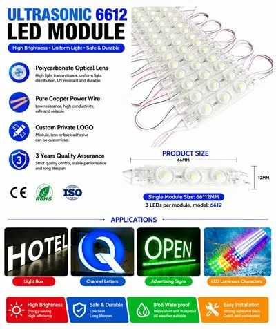
Hey there! As a supplier of the RGB Square 6led Module, I'm stoked to share with you how to make this awesome module display a color cycle. Whether you're into cool lighting effects for a party, a display, or just want to play around with some nifty tech, this guide is for you.
What You Need to Know About the RGB Square 6led Module
First off, let's talk a bit about the RGB Square 6led Module. It's a compact and powerful lighting module that comes with six RGB LEDs. RGB stands for Red, Green, and Blue, which are the primary colors of light. By mixing these three colors in different intensities, you can create a vast spectrum of colors. This module is super versatile and can be used in a variety of applications, from small DIY projects to large-scale commercial displays.
The Basics of Color Mixing
To understand how to create a color cycle, you need to know a bit about color mixing. Each RGB LED can emit red, green, or blue light at different intensities. By controlling the intensity of each color, you can mix them to create new colors. For example, if you turn on the red and green LEDs at full intensity and turn off the blue LED, you'll get yellow light. If you turn on all three LEDs at full intensity, you'll get white light.
The intensity of each color is usually controlled by a pulse-width modulation (PWM) signal. PWM is a technique that allows you to control the average power delivered to a device by rapidly switching it on and off. By varying the width of the pulses, you can control the intensity of the light.
Setting Up the Hardware
Before you can start creating a color cycle, you need to set up the hardware. Here's what you'll need:
- RGB Square 6led Module
- A microcontroller (such as an Arduino)
- Power supply
- Wires
Here's how to connect everything:
- Connect the power supply to the RGB Square 6led Module. Make sure to connect the positive and negative terminals correctly.
- Connect the control pins of the RGB Square 6led Module to the PWM pins of the microcontroller. The control pins are usually labeled as R (red), G (green), and B (blue).
- Connect the ground pin of the RGB Square 6led Module to the ground pin of the microcontroller.
Writing the Code
Now that you've set up the hardware, it's time to write the code. Here's a simple example of how to create a color cycle using an Arduino:
// Define the pins for the RGB LEDs
const int redPin = 9;
const int greenPin = 10;
const int bluePin = 11;

void setup() {
  // Set the pins as output
  pinMode(redPin, OUTPUT);
  pinMode(greenPin, OUTPUT);
  pinMode(bluePin, OUTPUT);
}

void loop() {
  // Cycle through the colors
  for (int redValue = 0; redValue <= 255; redValue++) {
    analogWrite(redPin, redValue);
    analogWrite(greenPin, 255 - redValue);
    analogWrite(bluePin, 0);
    delay(10);
  }

  for (int greenValue = 0; greenValue <= 255; greenValue++) {
    analogWrite(redPin, 0);
    analogWrite(greenPin, greenValue);
    analogWrite(bluePin, 255 - greenValue);
    delay(10);
  }

  for (int blueValue = 0; blueValue <= 255; blueValue++) {
    analogWrite(redPin, 255 - blueValue);
    analogWrite(greenPin, 0);
    analogWrite(bluePin, blueValue);
    delay(10);
  }
}
Let's break down the code:
- In the
setup()function, we set the pins for the RGB LEDs as output pins. - In the
loop()function, we use threeforloops to cycle through the colors. Each loop gradually increases the intensity of one color while decreasing the intensity of another color. - The
analogWrite()function is used to control the intensity of the LEDs. The value passed to the function can range from 0 to 255, where 0 means the LED is off and 255 means the LED is at full intensity. - The
delay()function is used to slow down the color cycle so that you can see the changes.
Customizing the Color Cycle
The code above creates a simple color cycle that goes from red to yellow to green to cyan to blue to magenta and back to red. However, you can customize the color cycle to create different effects. Here are some ideas:


- Change the speed: You can adjust the delay time in the
delay()function to change the speed of the color cycle. A shorter delay time will make the color cycle faster, while a longer delay time will make it slower. - Create different color patterns: You can modify the code to create different color patterns. For example, you can create a pattern that alternates between two colors or a pattern that fades in and out.
- Add randomness: You can add randomness to the color cycle to create a more dynamic effect. For example, you can randomly change the intensity of the LEDs or the direction of the color cycle.
Other Applications of the RGB Square 6led Module
The RGB Square 6led Module isn't just limited to creating color cycles. Here are some other applications:
- Billboard lighting: The LED Injection Module for Billboard can be used to create eye-catching lighting effects for billboards. You can use the RGB Square 6led Module to create dynamic color displays that attract attention.
- Backlighting: The AC220V LED Backlight Module can be used to provide backlighting for displays. The RGB Square 6led Module can be used to create colorful backlighting that enhances the visual appeal of the display.
Conclusion
Making the RGB Square 6led Module display a color cycle is a fun and rewarding project. By understanding the basics of color mixing and using a microcontroller, you can create a wide range of lighting effects. Whether you're a hobbyist or a professional, the RGB Square 6led Module is a great choice for your lighting projects.
If you're interested in purchasing the RGB Square 6led Module or have any questions about it, feel free to reach out. We're here to help you bring your lighting ideas to life.
References
- Arduino Documentation: https://www.arduino.cc/reference/en/
- Pulse-Width Modulation: https://en.wikipedia.org/wiki/Pulse-width_modulation