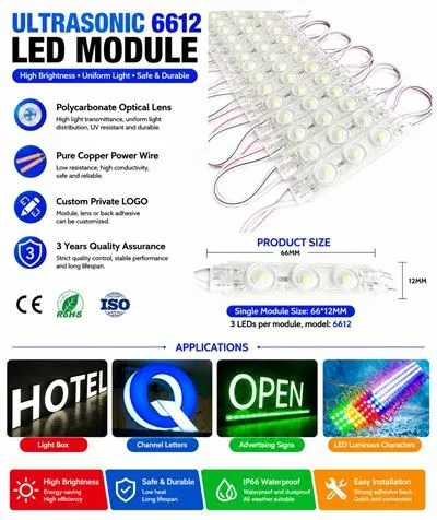
As a supplier of RGB 4LED Modules, I often receive inquiries from customers about how to replace a faulty LED in these modules. In this blog post, I'll share a comprehensive guide on this topic, which will be useful for both DIY enthusiasts and professionals in the lighting industry.
Understanding RGB 4LED Modules
Before we dive into the replacement process, it's essential to understand what RGB 4LED Modules are. These modules consist of four LEDs that can emit red, green, and blue light, allowing for a wide range of color combinations. They are commonly used in various applications, such as decorative lighting, signage, and backlighting.


Our company offers a variety of RGB 4LED Modules, including the 220V 4LEDS Module, 2led Modules for Signs, and AC110V 220V Led Backlight Module. Each module is designed with high - quality components to ensure long - term performance and reliability.
Tools and Materials Needed
To replace a faulty LED in an RGB 4LED Module, you'll need the following tools and materials:
- Soldering Iron: A good quality soldering iron with adjustable temperature is crucial. A temperature of around 350 - 400 degrees Celsius is usually suitable for soldering LEDs.
- Solder: Use a lead - free solder with a diameter of about 0.6 - 0.8mm.
- Desoldering Pump or Wick: This is used to remove the old solder from the LED pads. A desoldering pump is quick and easy to use, while desoldering wick can provide more precise removal.
- Tweezers: Fine - tipped tweezers will help you handle the small LED components.
- Multimeter: To test the new LED and check the electrical connections in the module.
- Replacement LED: Make sure the replacement LED has the same specifications as the faulty one in terms of color, voltage, and current ratings.
Step - by - Step Replacement Process
Step 1: Safety First
Before starting any work on the module, ensure that the power supply is disconnected. This will prevent any electrical shock or damage to the module.
Step 2: Identify the Faulty LED
Use a multimeter to test each LED in the module. Set the multimeter to the diode test mode and connect the probes to the two terminals of each LED. A working LED should show a forward voltage drop (usually around 1.8 - 3.6V depending on the color) and conduct current in one direction. If an LED shows no voltage drop or conducts in both directions, it is likely faulty.
Step 3: Desolder the Faulty LED
Heat the solder joints of the faulty LED using the soldering iron. Once the solder melts, use the desoldering pump or wick to remove the solder. Be careful not to overheat the PCB (Printed Circuit Board) as it can damage the traces or other components. Use the tweezers to gently lift the faulty LED from the PCB once the solder is removed.
Step 4: Clean the Pads
After removing the faulty LED, there may be some residual solder on the pads. Use the soldering iron and desoldering wick to clean the pads and make them smooth. This will ensure a good connection for the new LED.
Step 5: Install the New LED
Take the replacement LED and align it correctly with the pads on the PCB. Make sure the polarity is correct; most LEDs have a longer positive lead and a shorter negative lead. Hold the LED in place with the tweezers and use the soldering iron to apply a small amount of solder to each joint. Heat the pad and the lead of the LED simultaneously until the solder flows and forms a good connection.
Step 6: Test the New LED
Reconnect the power supply and use the multimeter to test the new LED. Check if it emits light and if the color and brightness are as expected. If there are any issues, double - check the soldering joints and the electrical connections.
Troubleshooting
If the new LED does not work after replacement, here are some possible causes and solutions:
- Incorrect Polarity: Make sure the LED is installed with the correct polarity. Reverse the LED if necessary.
- Poor Soldering Joints: Check the soldering joints for any cold solder joints (dry, dull, or cracked joints). Reheat the joints and add more solder if needed.
- Damaged PCB Traces: Overheating during desoldering or soldering can damage the PCB traces. Use the multimeter to check for continuity in the traces. If a trace is damaged, it may need to be repaired using a conductive pen or by soldering a jumper wire.
Maintenance Tips to Avoid Future Failures
- Proper Installation: Ensure that the RGB 4LED Modules are installed in a well - ventilated area and away from sources of heat and moisture.
- Regular Inspection: Periodically check the modules for any signs of damage or loose connections.
- Use Quality Power Supplies: A stable and appropriate power supply is essential for the long - term performance of the LEDs. Avoid using power supplies with voltage fluctuations.
Contact Us for Procurement
If you are interested in purchasing our RGB 4LED Modules or need further technical support, please feel free to contact us. We have a wide range of products to meet your different needs, and our professional team is always ready to assist you. Whether you are a small business looking for LED modules for signage or a large - scale project requiring backlighting solutions, we can provide you with high - quality products and excellent service.
References
- LED Lighting Handbook, Third Edition, by Michael Krames, et al.
- Printed Circuit Board Design and Assembly Guide, by IPC (Association Connecting Electronics Industries)